
Instrumentation IO drawings are vital in electrical system design showcasing the input and output of instruments within control systems. These drawings, packed with critical information, detail the wiring interconnections for IO analog and digital control points, enclosures, terminal strips, and terminal blocks. Traditionally, creating and maintaining these detailed documents is a time-consuming task. This article explores how SaaS Electrical can automate the production of IO drawings, whether for small projects or entire facilities, using a consistent and efficient workflow.
DIAGRAMS automatically drafts LOOP drawings directly from SOCKETWorx as a Service (SaaS) Electrical by creating and uploading AutoScripts. SaaS shifts electrical design and engineering to the cloud. DIAGRAMS communicates with the cloud produce AutoCAD® drawings using collections of routes, symbols, and groups saved as AutoScripts.
IO drawings are relatively complex electrical system design drawings. Complexity compounds as control point wiring passes through enclosure terminals demanding more cables. DIAGRAMS is able to satisfy IO drawing demands.
 Default Symbology naming conventions
IO Symbols are divided into four groups: 1756 ALLEN BRADLEY CARDS, 1756 ANALOG IO, 1756 DIGITAL INPUTS, and 1756 DIGITAL OUTPUTS.

IO AutoScript naming conventions are based upon the IO configuration and device type.

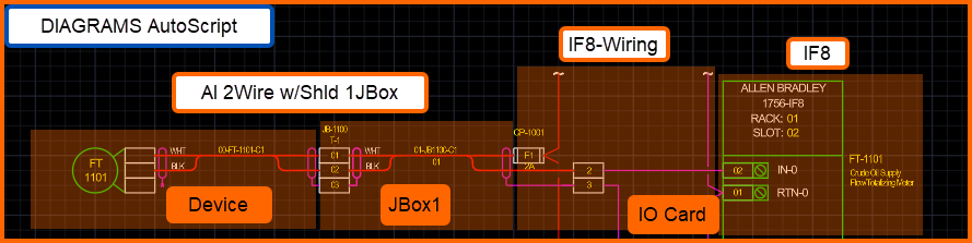
This example shows 'AI 2Wire wShld 1JBox Device' with 'AI 1756-IF8' and is comprised of 3 DIAGRAMS symbols: AI 2Wire w/Shld 1JBox, IF8-Wiring, IF8.
Here is the normal data entry workflow:
- Add instruments into SaaS Electrical
- AutoScript - IO Drawing worksheet.
- Assignments - IO Card and Device Cabling
- Assigning DIAGRAMS AutoScripts and drawing positions
- Batch DIAGRAMS drawings from SaaS Electrical
This article is a step-by-step guide on how to enter data and ultimately use DIAGRAMS to produce drawings using the DIAGRAMS AutoScript technology.
The demonstration video offers a live view of the process from start to finish.
Contact ECE to set up SaaS Electrical pilots project against your use cases.
Demonstration Video
Step 1 - Add Instruments into SaaS Electrical
SaaS Electrical includes a set of standard Assignment and AutoScript data views under Electrical System Design table.
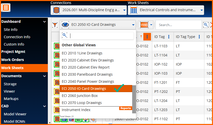
Each view contains a set of columns that satisfy respective data requirements. Navigate to ECI 2050 IO Card Drawings to add rows that will represent instruments within your electrical control system.
Adding Instruments
There are numerous Header Controls that support data entry, reporting, document attachment, and document associations. The first task is to add new rows to projects. Up to 1000 rows can be added, but generally users are adding rows in quantities relative to the scope of work.

Launching Worksheet Mode.
Once 'NewRows' are added, launch worksheet mode to enter data.

ID Tag, column C shown below, is a concatenation field. ID Tag is populated by the concatenation of ID Tag Type and ID Tag Number. Therefore, ID Tag is non-editable and is only populated by entering the values for ID Tag Type and ID Tag Number.
Columns with colorized backgrounds are locked for various reasons like this. In this case, the data must be saved then reloaded to update ID Tag. All the columns represent instrument properties that are visible in IO drawings.
IMPORTANT: Column B, or the filename column, must be populated with a filename that DIAGRAMS will use to produce AutoCAD *.dwg files.

Once all the data has been saved in these Assignment worksheets, the IO drawings are ready to be created.
The next step is to make the DIAGRAMS AutoScript assignments to all the instruments.
STEP 2 - Assigning DIAGRAMS AutoScripts and drawing positions
DIAGRAMS contains numerous electrical and control system symbols suited for manual and automated drafting.
Users draft collections of DIAGRAMS Routes, Symbols and Groups and upload them to SOCKETWorx as SaaS Electrical AutoScripts. The default symbol offering is available at saas.socketworx.com where trial access can be granted to explore it and uploading custom AutoScripts.
Enabling AutoScript Views
AutoScripts are assigned to rows within SaaS Electrical Data Views, when their Automated Script option is active.
Edit Data View setups to find that setting.

Assign AutoScripts to instruments one-by-one
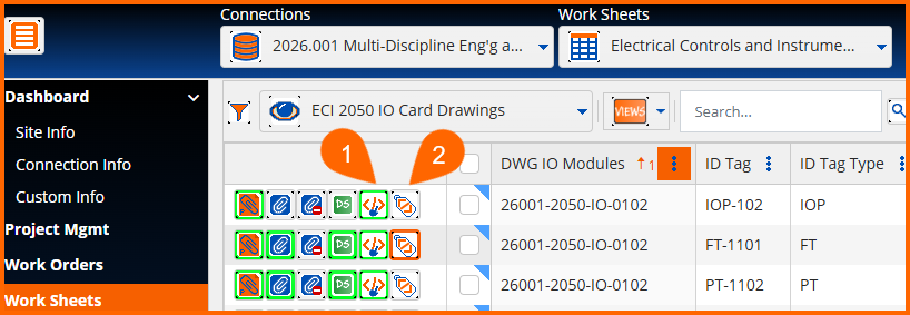
Once active, two row control buttons appear.
(1) AutoScript Assignment
One click launches the AutoScript Assignment popup window.
Select one and close.
(2) AutoScript Datasheet
One click launches the AutoScript Datasheet popup window.
Enter the AutoScript insertion point X and Y drawing file coordinates.
Review all visible AutoScript drawing annotation and attribute sourced from the data row.
Optionally, override data coming from the source row, and close.
Row controls are used to make changes one-by-one, and the header controls enable bulk updates.
A single row will represent the card portion of the drawing. Two cards may be present on one drawing. A single row will also represent each device on the card. For example, 26001-2050-IO-0102 has two cards with devices. The first card and device are highlighted.

Assign AutoScripts to instruments in Bulk
Prior to updating in bulk, it is helpful to filter using the global or column options. If the Data View is limited to a target group, the column 1 header 'check-all' can be used. Otherwise, multi-select rows by using the checkboxes.

Begin bulk updates by choosing an option. Generally, it is recommended to work from top to bottom workflow.
Bulk Assign:
Drawing Script Templates. The DWG IO Modules Column lists all the drawing files to produce. This option launches the Assign Drawing Template popup window with a distinct list of drawings with a row control button to pick one.

Drawing Titleblock Information. New feature preview at the time of this article and only support electrical ladder diagram rung numbering.
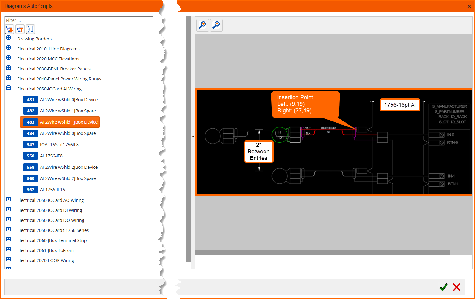
AutoScripts. Launches the assignment popup window. It offers AutoScripts in groups. Use the global filer to search by name or scroll through the groups. Once selected, the associated image displays to aid in the selection process.
Clear AutoScripts. Remove the association but preserves the drawing XY coordinates.
Drawing Positions. Launches the bulk edit popup window. The first four columns are presented along with Columns G and H. These are the only editable columns where X and Y Offsets from AutoCAD World Coordinate System (0,0). This provides the instructions for DIAGRAMS to insert at these coordinates them automatically.
Once rows have filenames and AutoScripts assigned, DIAGRAMS will produce drawings from the data
STEP 3 - Batch DIAGRAMS drawings from SaaS Electrical
Create New Projects
DIAGRAMS is designed to enable drafting from its default symbol library within any AutoCAD drawing file.
However, the AutoScript processor requires a project be set that it is set to use the default Configuration and SymbolLibrary XML files. AutoScripts can be run from projects with or without databases. Consider that a database is required to join off-page connectors, and bulk update from the Project Manager.
Reference these legacy self-help content on creating new projects:
https://support.ecedesign.com/en/support/solutions/articles/24000091888-creating-projects
After creating new projects, open them by using the DIAGRAMS Control Center palette from AutoCAD®
Next launch the SOCKETWorx AutoScript panel (2), browse to a SaaS Electrical Connection (3), select a Script View (4), and double click on Drawings (5) to create them.

If drawings are already open or already exists within the project, an option dialog will display with options to clear and recreate it.