

Single Lines or One Lines (1Line) illustrate power distribution equipment such as cabinets, enclosures, controllers, and a host of eletromechanical prime movers.
This article presents setups and methods combined into a standard engineering procedure that produces DIAGRAMS from SOCKETWorx and its SaaS Electrical Data Worksheets.
SOCKETWorx as a Service (SaaS) shifts electrical design and engineering to the cloud, and DIAGRAMS communicates with it to produce AutoCAD® drawings from corporate symbology from any CAD workstation globally.
The standard drawing procedure workflow:
- Adding and populating electrical load information into
SWx Elec Control Points - Assigning AutoScripts and drawing information into
SWx Elec Control Points - Batching AutoCAD drawings from CAD Workstations using DIAGRAMS.
The step-by-step procedure trains users to enter engineering information using SOCKETWorx Data Worksheets. It transitions into training on the procedures to batch drawings, where DIAGRAMS and its AutoScript symbol technology are used.
The demonstration video offers an overview of the procedure from start to finish.
Demonstration Video
STEP 1 - Adding Electrical Loads and Entering Engineering Information
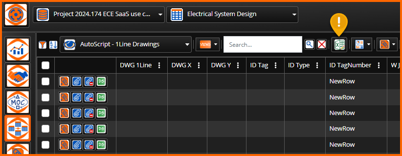
SaaS Electrical includes a set of standard Assignment and AutoScript data views for the Electrical System Design table.
Each view contains a set of columns that satisfy respective data requirements. Navigate to AutoScript - 1Line Drawings to add rows representing components of an electrical system.

Add Rows
Numerous Header Controls support data entry, reporting, document attachment, and document associations. The first task is to add new rows to projects. Up to 1000 rows can be added, but generally users are adding rows in quantities relative to the scope of work. In this example, we'll add 20 rows, representing 20 electrical equipment assets.

Launch Worksheet Mode.
Entering data is accomplished by launching worksheet mode.
Enter the ID_Type and ID_TagNumber because they are concatenated to form the ID_Tag. Columns with colorized backgrounds are locked for various reasons like this. In this case, the data must be saved then reloaded so the ID_Tag will update.
Next, assign each motor to a 1Line drawing by populating DWG_1Line. Enter the DWG_X and DWG_Y values for each. In this example, the X values start at 5 and increment by 3 up to 23. The Y values are all 20.5 because that is where the bus bar exists within the border template being used.
Important. Every drawing from SaaS Electrical can have a border template assigned, with user-defined settings and content to enhance further drawing content, like a bus bar in this example.
Other columns service reporting and drawing annotation requirements, so complete them.
Procedurally, populating these columns is enough data so DIAGRAMS can produce drawings.
ProTip: Save Changes!
STEP 2 - Assigning AutoScripts and setting drawing positions
The DIAGRAMS symbol library contains many AutoCAD blocks saved as electrical symbology.
They are set up so users can design drawings manually by inserting symbols one by one or automate them by connecting to SaaS Electrical and its AutoScripts.
Important. DIAGRAMS creates AutoScripts by selecting one or more DIAGRAMS symbols and uploading them to SOCKETWorx. Uploaded AutoScripts are then consumed and otherwise managed using SOCKETWorx.

Manually draft a collection of DIAGRAMS Routes, Symbols, and Groups, then upload to SOCKETWorx as uniquely named AutoScripts.
Enable 'Automated Script' on SWx Control Point Data Worksheets.
AutoScripts are assigned to rows within SaaS Electrical Data Worksheets in bulk using the control headers, or individually using the row controls. First, Data Worksheets must be enabled, as shown here.

Set AutoScript Parameters one-by-one
Once active, two more row control buttons will appear on Data Worksheets.
(1) AutoScript Assignment.
One-click launches the AutoScript Assignment popup window.
Select one and close.
(2) AutoScipt datasheet
One-click launches the AutoScript Datasheet popup window.
Enter the AutoScript insertion points; X and Y drawing file coordinates.
Review all visible AutoScript drawing annotations and attributes sourced from the data row.
Optionally, override data coming from the source rows, and close.

Row controls can be used to make changes one-by-one, and the header controls enable bulk updates.
Set AutoScript Parameters in Bulk
Before updating in bulk, it is helpful to filter using the global or column options. If the Data View is limited to a target group, the column 1 header 'check-all' can be used. Otherwise, multi-select rows by using the checkboxes.
Begin bulk updates by choosing an option. Generally, it is recommended to work from top to bottom in this workflow.
Bulk Assign:
Drawing Script Templates. The DWG 1Line Column lists all the drawing files to produce. This option launches the Assign Drawing Template popup window with a distinct list of drawings with a row control button to pick one.
Drawing Titleblock Information. A new feature preview only services electrical ladder diagram rung numbering.
AutoScripts. Launches the assignment popup window. It offers AutoScripts in groups. Use the global filter to search by name or scroll through the groups. Once selected, the associated image is displayed to help with selection and other spatial parameters like the offsets between AutoScripts.
Clear AutoScripts. Removes the association but preserves the drawing XY coordinates.
Drawing Positions. Launches the bulk edit popup window. The first four columns are presented along with Columns G and H. These are the only editable columns where X and Y Offsets from AutoCAD World Coordinate System (0,0). This provides the instructions for DIAGRAMS to insert at these coordinates them automatically.
Once rows have filenames and AutoScripts assigned, DIAGRAMS will produce drawings from the data.
STEP 3 - Batch DIAGRAMS drawings from SaaS Electrical
Create New Projects
DIAGRAMS is designed to enable drafting from its default symbol library within any AutoCAD drawing file.
However, the AutoScript processor requires a project to be set that it is set to use the default Configuration and SymbolLibrary XML files. AutoScripts can be run from projects with or without databases. Consider that a database is required to join off-page connectors, and bulk update from the Project Manager.
Reference this self-help content on creating new projects:
https://support.ecedesign.com/en/support/solutions/articles/24000091888-creating-projects
After creating new projects, open them using the DIAGRAMS Control Center palette. Launch this palette from within the Diagrams ribbon tab Setup section.

Next, launch the SWx AutoScript panels.

Select a source SaaS Electrical Connection, a Script View, and one or more drawings to create.
Double-clicking on Drawings will launch the Create processor. If that drawing is open,, or already exists within the project, an options dialog will display requesting action to cancel or overwrite.
