
DIAGRAMS includes a tool to convert Lines and Polylines from legacy digital P&ID drawings, into DIAGRAMS Routes.
Conversion Tool Set-Up
The following steps will walk through the options for how the tool behaves
- Open the Worx Settings Form
- Navigate to Import Drawing Database Setup
- Choose your Database configuration
- Generally "No Database" will be used unless importing data from a MS Access or SQL Direct server
- Include which items from legacy drawings you wish to import
- "Routes" will include lines and polylines
- "Blocks" will include symbols and bubbles
- "Standard Lines" will include instrument, equipment and other non-process related lines
- "Gap Size" is
- "Excluded Blocks" will allow you to add block names and layers to exclude from the import
- Layers in the source drawing will be imported to chosen DIAGRAMS layers, this process will be explored below
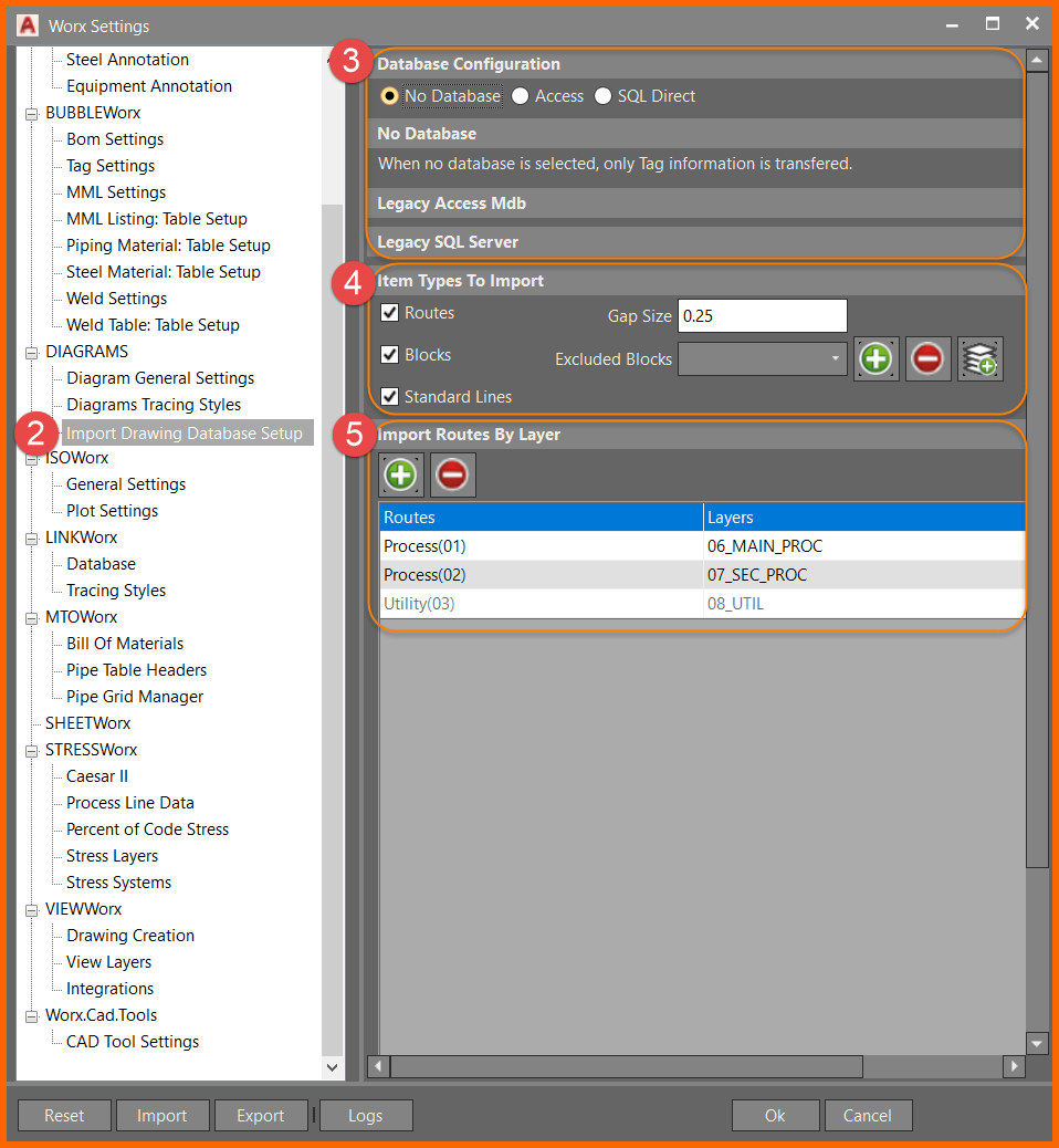
Set-Up Part 2: Import Routes By Layer
The following steps will walk through the process of adding routes to import
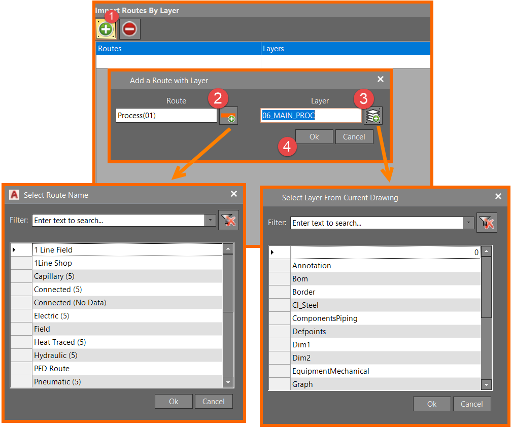
- Click the "Add Route/Layer Combo" button at the top of the "Import Routes By Layer" window
- If you know the Route Type you're importing to you can type it in the Route box or click the button to open a dialog to choose from available Route Types.
- If you know the layer you're importing from you can type it in the Layer box or click the button to open a dialog to chose from available layers in the drawing currently open.
- Click the OK button and the Route/Layer combo will appear in the window.
Running the Conversion Tool
Now that DIAGRAMS knows which layers to import and which route types to add to, now the tool can be used to import data from an AutoCAD .DWG file.
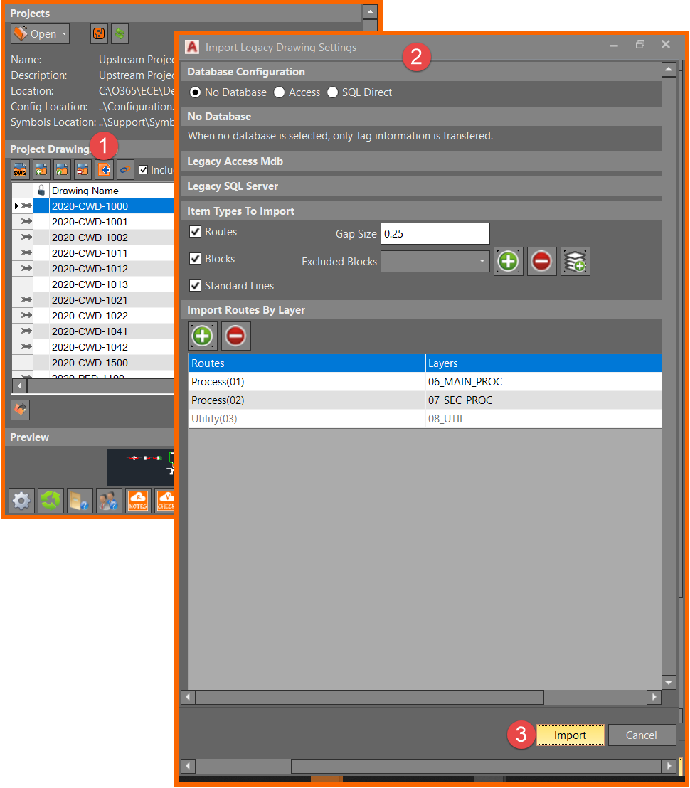
- Click the "Import Legacy" button in the DIAGRAMS Control Center
- The settings made during the set up portion of this guide will be reflected in the "Import Legacy Drawing Settings" window that appears
- Click the "Import" button at the bottom of the window to chose a file for the Conversion Tool to process, this may take some time depending on the size of the file.
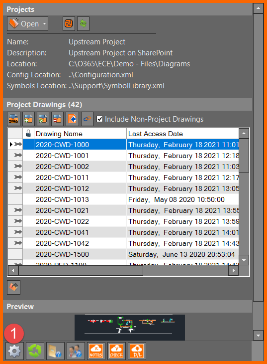
- A new Project Drawing will appear in the Control Center with all imported routes and geometry
Post-Conversion Clean-Up
After converting a legacy drawing to a DIAGRAMS drawing, there may be additional steps needed. Following are some tips to look out for after converting.
- Most line segments will be separated into their own ID. The "Data Join" command under Utilities - Routes in the DIAGRAMS ribbon should be used to join the individual segments of a line
- Components such as flanges, caps, valves, sometimes sections of equipment may be imported as process lines
- Imported blocks and symbols such as valves and instruments should be associated to their lines using the "Associate Symbol" command under Utilities - Associate in the DIAGRAMS ribbon