This content describes some actions that users should take before converting CADWorx piping specs into AutoCAD PLANT 3D piping specs using SPECWorx. ECE welcomes the opportunity to help with the conversion process including some of these necessary actions to prepare CADWorx content for the conversion process.
Component categories to work on:
TABLE OF CONTENTS
- Prepare Project File for Processing
- EndType Assignment
- Reducing Sizes
- TOPWorks
- Usershapes
- Flange Facing
- Short Descriptions
- Nipples & Swages
- Bleed Rings
- Bolt sets
- Clamps
- Strainers
Prepare Project File for Processing
In general, a CADWorx spec component must be completely filled with data in order to generate Plant 3D spec components.
These data items include:
- Schedule Assignment
- Material Assignment
- Endtype
- PressureClass
- Short Description
Information about these items, and additional items requiring editing are outlined below.
EndType Assignment
All components must have end types assigned, including usershape components.

Reducing Sizes
Specifications MUST be set to "Use Main Size"

TOPWorks
SPECWorx will process CADWorx (CWX) Project Files and transform Topworks Catalog Data if it exists. If there are Description and Short Description property values they will be converted. Populating these values prior to SPECWorx processing is highly recommended.
SPECWorx converts these Properties to AutoCAD PLANT 3D (P3D) Long Description (Family) and Short Description fields.
NOTE: In the CADWorx PRJ, a Valve must be assigned a Topworks for the valve to support an actuator in Plant 3D.
NOTE: TOPWorx conversion is supported for Prjs built-in CADWorx 2017 or later. Earlier version Prjs will have to be upgraded to support this feature.
Usershapes
SPECWorx will process CADWorx Project Files and transform Usershape Catalog Data if it exists. Data-wise Usershapes are processed like most other parts, but in order for them to load into AutoCAD PLANT 3D User must enhance the Usershape Project files by adding two Custom Data fields.
Users must add PNPCLASSNAME and PARTCATEGORY fields as Project Custom Data.
Note: If these fields are added to a Spec, they will not be processed. They must be added as Project Custom Data
Note: Fields are CASE SENSITIVE. eg, "INSTRUMENTS" will not work, but "Instruments" will.
These values originate in AutoCAD PLANT 3D as Basic Part Family Information.
The Component Category is the PARTCATEGORY, and the Piping Component is the PNPCLASSNAME.
Here are the permissible Component Categories and their permissible Piping Component values that must be entered into CADWorx PRJ files prior to SPECWorx processing. If these values are not entered, then SPECWorx will not process Usershapes
Note: SPECWorx will not process Usershapes into the Valve Part Category.
 |  |  |
 | ||
 |  |  |

Flange Facing
SPECWorx will process CADWorx Project Files and transform Flanged components. Data-wise Usershapes are processed like most other parts, but in order for them to load into AutoCAD PLANT 3D User must enhance the Usershape Project files by adding custom data for the Facing in one of two locations.
Flange Facing is a dominating parameter in P3D Piping Connection Settings. Keep in mind that facing also comes into play for Grooved type connections as well.

Since CWX does not have a property that directly corresponds to the P3D FACING, it must be added to either the CWX Catalog Data Table Custom Data or the CWX Project Custom Data.


SPECWorx will Convert the values like this.
If FACING values are found in the CWX Catalog Data as Custom Data, then those values are converted. If no value is found in CWX Catalog Data, then SPECWorx searches for FACING values in Project Custom Data. If no values exist in either location, then FACING will not be populated and Users will have to populate this value post-conversion using the P3D Spec Editor.
Short Descriptions
CADWorx Short Descriptions are loaded into the P3D Short Description field. They are mandatory because if left blank, or empty, P3D will crash while routing pipe and using the PipeFitting option.

It is worth noting that P3D offers interface enhancements where Short Descriptions are used to present parts for placement effectively.
CADWorx can be configured so that the Spec View palette will display either Long or Short descriptions, so once selected as a setting that is the only description users will see.
On the other hand, P3D does not offer interface adjustments. However, Short Descriptions are used as selection variables in every portal. The P3D interface does a good job presenting Long Descriptions so users can accurately choose parts.
While routing pipe, users can select a 'Fittings' option which launches a selection interface.
Many users rely on the Dynamic Pipe Spec Tab on the Piping Components palette and here Short Descriptions are followed by End Type, Pressure Class, Facing, Schedule, and Spec Ref helping users identify the right part.
SPECWorx users should consider the Short Description role in the P3D piping specs and consider tailoring them. This is important because users will be interacting with them on every transaction.
Nipples & Swages
SPECWorx users need to consider that CWX and P3D handle End Types differently.
CWX enables uses to set end conditions when routing Pipe 'on the fly' on the routing command prompt.
P3D basically requires that fittings exist in the catalogs and specs with end types predefined.
What does all this have to do with converting pipe specs from CWX to P3D? Actually, it is very important because P3D is more of a Spec-Driven application than CWX in the fact that P3D requires Nipples and Swages exist in the catalog and specifications where components with BBE, PBE, TSE, POE-TOE, TLE-PSE, etc. end types exist.
It is highly recommended to address this in the CWX spec prior to converting them.
As a best practice, it becomes important to add the end types to the long descriptions so users can easily find the components they are wanting to place inclusive of their end conditions.
Optional settings in CWX would automatically append developed long descriptions with end conditions. P3D does not do this, so putting that information towards the beginning of long descriptions or including them in short descriptions can be beneficial to users.
Bleed Rings
SPECWorx will process Bleed Rings and translate these items over into a Plant 3D component. However, the details required to produce the bleed ring differ in CADWorx and Plant 3D, where we can add additional information on the Plant 3D side. A bleed ring will typically contain at least one tapping point on the ring, but in CADWorx there is no way to add a tap point on the item itself.
To address this limitation, in CADWorx Specification Editor a user can add a Custom Data Field on the Bleed Ring Catalog Data tables for "OTN" and "OTD", which SPECWorx can then reference the tap point number (OTN) and tap point diameter (OTD).
Add the custom data to the data table as TEXT items.
Example:
OTN = 2
OTD = 0.25
SPECWorx will convert a bleed ring with these values into a part in Plant 3D with 2 Taps, 1/4" OD.
Only by adding these fields can we properly transfer the bleed ring information including tap points over into Plant 3D.
However, if these values are not present, Bleed Rings will default to having no tap points, similar to how these items appear in CADWorx.
Please note, the same Custom Data fields for OTN or OTD can be added to Flanged items, in order to create Orifice Flanges.
TOP OF PAGE
Bolt sets
SPECWorx will process bolt sets and convert them into P3D as Fasteners. In order to get bolt sets to convert successfully, the user must do the following:
- CADWorx Short Descriptions must be unique for each bolt component in the CADWorx *.prj that is converted.
During conversion, SPECWorx will perform the following operations on Bolt Sets.
- Unique CADWorx Short Descriptions are converted into Plant 3D Part Families.
- The CADWorx Short Description becomes the P3D PartFamilyLongDescription.
- The CADWorx Long Description for each bolt component becomes the PartSizeLongDescription.
Consider using the CADWorx field for "Component Class", or "Index Code" to stratify bolt short descriptions into unique P3D PartFamilyLongDescription components.
Because CADWorx configurations most often include unique bolt lengths or unique bolt diameters within a Long Description, it makes sense for them to become the P3D PartSizeLongDescription within P3D.
!!! Warning !!! - If you do not make your CADWorx bolt short descriptions unique, bolts will be combined into a single P3D Part Family.
See the image below for an example of unique short descriptions for bolts. These bolts will become three unique P3D Part Families, because their short descriptions are unique.

Clamps
SPECWorx will process CADWorx Project Files which will transform Couplings and convert them into P3D as Fasteners. Program Code 39 components can have an overlay and SPECWorx will need to meet several criteria for the shapes to be processed into AutoCAD Plant 3D. Besides Program Code 39, the User will be required to use a specific SKEY and populate the DWGNAME field in the CADWorx Catalog Data Table.
For Tri-clamp connections:
Program Code - 39
SKEY - CLMP
DWGNAME - 'VALUE'
For Victualic clamp connections:
Program Code - 39
SKEY - CLVT
DWGNAME - 'VALUE'

Strainers

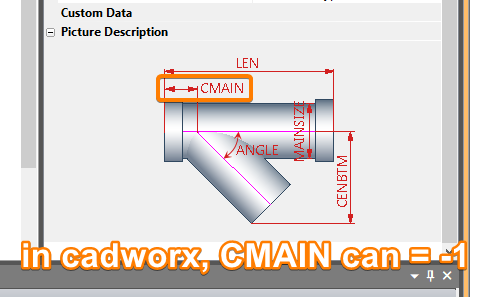
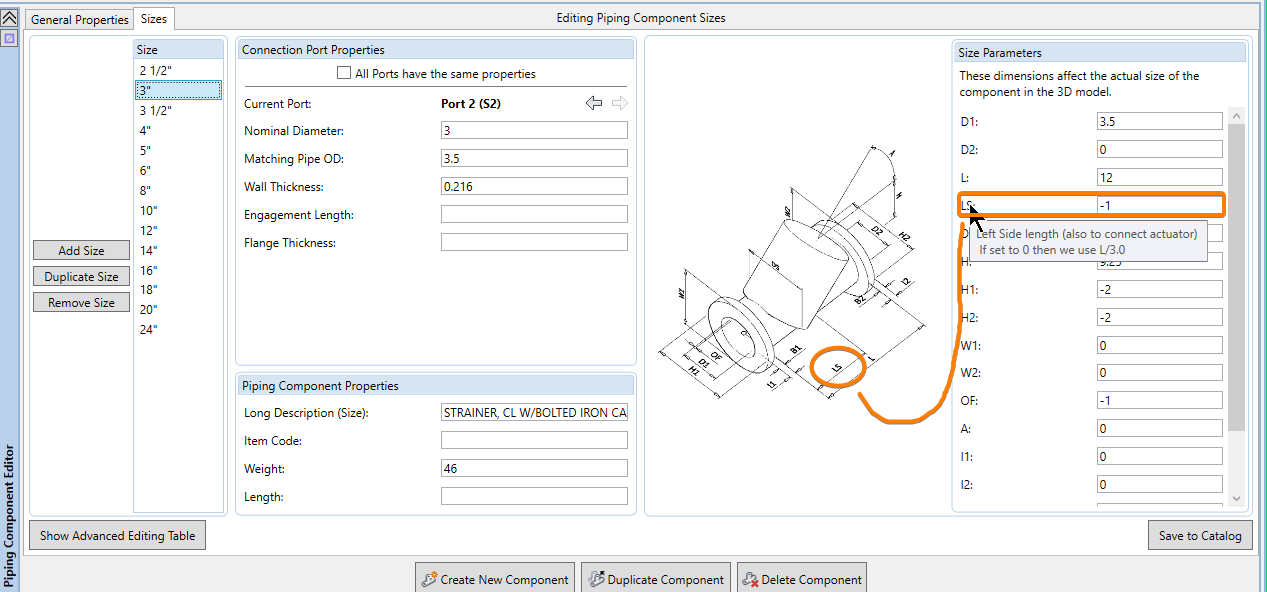
SPECWorx will interpret "-1" as "0" in plant 3d, and any other value will be interpreted as a number. This allows users to position the leg where they want, if it is specified with a number.


